Medical Devices
Cardiac Devices, Testing, and Design
Since the invention of the implantable pacemaker in the late 1950s, cardiac device development has exploded. Devices now, in part, include catheters, pacing systems, implantable valves, sensors, stents, defibrillation systems, and delivery systems for drug or cell therapies. Importantly, prior to production and market release, these devices must undergo rigorous testing. Often, device designs begin as a rudimentary prototype and must be revised numerous times to be effective and easy to use.
Continue Reading
We typically perform comparative or complementary studies, both in situ and in vitro [1]. Frequently, cardiac devices are placed both in situ and in vitro within the same animal heart; the ability to conduct experiments in both environments gives us valuable insights as to how such devices may perform in patients. More specifically, our in vitro methods involve isolating the heart and connecting it to the Visible Heart® apparatus, where the heart will beat on its own [2,3]. The heart is supplied with a clear perfusate that provides nutrients and oxygen to enable the heart to sustain its intrinsic rhythm (Figure 1). See visibleheart.com for more details.
With the Visible Heart® methodologies, we can directly visualize cardiac devices within the beating heart. For example, different shaped catheters can provide easy access to certain targeted regions of the heart for implanting pacing leads. The Visible Heart® allows direct visualization of these catheters and provides information on what target sites within the heart clinicians can most easily reach.
Additionally, the Visible Heart® approach allows for observation of the device-tissue interface. For instance, in a recent study, we implanted active fixation pacing leads a specified number of helix rotations, then observed how the rotating helix affected the myocardial tissue with each rotation [4,5]. We found that too many rotations could result either in the myocardial tissue “wrapping” around the tip of the pacing lead (Figure 2) or “coring” the tissue such that the pacing lead was not attached to any myocardial tissue.
The Visible Heart® methodologies not only enable direct visualization of cardiac devices within the heart, but also allow direct visualization of relative cardiac anatomy. Recently, our labs published the first directly visualized pictures and videos of Thebesian valves and other venous valves [6,7,8]. The majority of previous studies observing these valves utilized cadavers; with clear perfusate employed in the Visible Heart® approach, we visualized movements of these valves throughout the cardiac cycle. We also observed a large amount of variability among hearts and have been among the first researchers to report such findings [6,7,8]. An example is pictured below in Figure 3 of a valve of Vieussens, which delineates the coronary sinus and the great cardiac vein [8].
We believe that future studies of cardiac devices using the Visible Heart® methodologies will continue to provide important insights relative to cardiac device design. As cardiac devices become more sophisticated, the design and testing of these devices will be even more critical to ensure that the devices improve quality of life for patients that may present with a variety of cardiomyopathies.
Figure 1. Isolated human heart connected to the Visible Heart® apparatus
Figure 2. A pacing lead (Select Secure™ Lead System Model 3830, Medtronic, Inc.) implanted in the right atrial appendage with tissue wrapped around the pacing lead tip.
Figure 3. The valve of Vieussens in this heart was a unicuspid leaflet covering the ostium to the great cardiac vein (GCV). Left ventricular venous ostia and the ostium of the posterior vein of the left ventricle (PVLV) are also visible.
- Laske TG, Skadsberg ND, Iaizzo PA: A novel ex vivo heart model for the assessment of cardiac pacing systems. Journal of Biomechanical Engineering 127: 894-898, 2005.
- Chinchoy E, Soule CL, Houlton AJ, Gallagher WJ, Hjelle MA, Laske TG, Morissett J, Iaizzo PA: Isolated four-chamber working swine heart model. Annals of Thoracic Surgery 70: 1607-1614, 2000.
- Hill AJ, Laske TG, Coles JA Jr, Sigg DC, Skadsberg ND, Vincent SA, Soule CL, Gallagher WJ, Iaizzo PA: In vitro studies of human hearts. The Annals of Thoracic Surgery 79: 168-177, 2005.
- Laske TG, Vincent SA, Skadsberg ND, Iaizzo PA: High pacing impedances: Are you overtorquing your leads? Pacing and Clinical Electrophysiology 28: 883-891, 2005.
- Anderson SE, Skadsberg ND, Laske TG, Benditt DG, Iaizzo PA: Variation in pacing impedance: impact of implant site and measurement method. PACE, 30: 1076-82, 2007.
- Hill A, Coles JA Jr, Sigg DC, Laske, TG, Iaizzo PA: Images of the human coronary sinus ostium obtained from isolated working hearts. The Annals of Thoracic Surgery 76: 2108, 2003.
- Hill AJ, Ahlberg SE, Wilkoff BL, Iaizzo PA: Dynamic obstruction to coronary sinus access: the Thebesian valve. Heart Rhythm 3: 1240-1, 2006.
- Anderson SE, Hill AJ, Iaizzo PA: Venous valves: unseen obstruction to coronary sinus. Journal of Interventional Cardiac Electrophysiology (in press) 2007.
Visible Heart®: Functional Cardiac Anatomy using a 4-chamber Isolated Heart Preparation of Various Large Mammalians including Human Hearts
The Visible Heart® isolated heart project evolved from a joint collaboration established in 1997 between the University of Minnesota and Medtronic, Inc. This ongoing research collaboration has resulted in a working four-chamber isolated cardiac model that can simulate in situ physiological cardiac function. This beating heart model has provided an opportunity to simultaneously capture internal images of a working heart on video while recording various physiological parameters, such as electrical potentials, pressure volume changes, ejection fractions, flows, etc. The Visible Heart® methodology is considered an invaluable tool in understanding the relationship between cardiac anatomy and function, as well as the interaction between cardiac anatomy and device therapies.
Continue Reading
The functional anatomy provided by the Visible Heart® approach is a useful tool for:
- identifying general pathophysiology (congenital defect, atherosclerosis, valvular defect, etc.);
- performing comparative anatomical studies of functioning human and animal hearts;
- observing device interactions (leads, catheter, valves, stents, septal occluders, etc.);
- obtaining simultaneous external and internal images and conducting comparative image analysis (fluoroscope, endoscope, echo, high-speed, fiberscope); and
- educating physicians and/or students (via lab visits, live-web cast capabilities, or educational materials).
After a standard cardioplegia procedure, the heart is reanimated by first reperfusing the myocardium in a Langendorff perfusion mode via a constant hydrostatic pressure [1,2]. Langendorff perfusion is necessary since the initially static heart cannot generate any pressure to supply the coronary arteries. All hearts are perfused with a modified, transparent Krebs-Henseleit buffer solution as described in reference [3]. The transparency of the perfusate is one of the main features that enables the visualization of functional cardiac anatomy. After defibrillation, the heart can be placed in a four-chamber working mode in which physiologic preloads and afterloads can be adjusted to best simulate in situ cardiac function. With all chambers functioning in a simulated physiological environment, specialized endoscopes and fiberscopes are utilized to view intracardiac functional anatomy. These methodologies also allow for simultaneous intracardiac and external visualization of a beating heart as well as visualization of valve action, contraction of atria and ventricles, and the architecture of the heart as it beats. These methodologies are an invaluable tool for visualizing the intimate relationship between form and function.
To date, human, pig, mini-pig, dog, and sheep hearts have been reanimated using these methodologies. Physiologic assessment of the model is summarized for animal and human hearts in references [3] and [4] respectively. For more details and images, refer to The Atlas.
- Langendorff, O. Untersuchungen am überlebenden Säugethierherzen. Pflügers Arch. ges. Physiol. 61: 291, 1895.
- Dehnert H. The Isolated Perfused Warm-Blooded Heart according to Langendorff. Methods in Experimental Physiology and Pharmacology: Biological Measurement Techniques V. Biomesstechnik-Verlag March GmbH, West Germany. 1988.
- Chinchoy E, Soule CL, Houlton AJ, Gallagher WJ, Hjelle MA, Laske TG, Morissett J, Iaizzo PA: Isolated four-chamber working swine heart model. Annals of Thoracic Surgery 70: 1607-1614, 2000.
- Hill AJ, Laske TG, Coles JA Jr, Sigg DC, Skadsberg ND, Vincent SA, Soule CL, Gallagher WJ, Iaizzo PA: In vitro studies of human hearts. Annals of Thoracic Surgery 79: 168-177, 2005.
Electrophysiology, Surface, and Noncontact Mapping
Heart rhythm disorders are a major cause of morbidity and mortality in the United States. Sudden cardiac death, usually caused by ventricular arrhythmias, is the leading cause of death in the US. Cardiac electrophysiology (EP) is the study of the electrical rhythms of the heart, and its goal is to understand and treat abnormalities associated with heart rhythm disorders.
Continue Reading
Our labs uses a multi-level approach to understand cardiac electrophysiology. At a single-cell level, we can record action potentials and various ion channel currents using both intracellular microelectrode and patch-clamp techniques. We have recently characterized many ion channel currents in the HL-5 cardiomyocyte immortalized cell line [1]. On a multi-cellular level, cardiomyocytes are cultured on a micro-electrode array which allows us to visualize the two-dimensional propagation of electrical activity at the micron scale.
In large animal models, our labs employ both surface mapping and noncontact mapping of the swine heart in vivo. Surface mapping is performed in collaboration with Dr. Bin He in the Department of Biomedical Engineering at the University of Minnesota. During surface mapping, a matrix of surface electrodes is placed on the chest of the swine and EKG signals are recorded from the electrodes. Later, the animal undergoes an MRI to collect anatomical data. During post-processing, the electrical propagation in the heart is calculated within an anatomically correct model.
In our laboratories, we are using noncontact mapping to study endocardial activation in normal and diseased states (i.e., dilated cardiomyopathy, acute myocardial infarction) as well as during cardiac pacing. Currently, we are using the mapping system developed by Endocardial Solutions, Inc. to map the left ventricle. The system employs a multielectrode array catheter with 64 electrodes and a balloon internal to the cateheter which is inflated with a saline-contrast mixture (50%-50%) and placed into the left ventricle. Computer software calculates the position of a standard EP catheter in relation to the multielectrode catheter for the purposes of endocardial geometry definition. Once the geometry is known, the virtual endocardium is divided into more than 3,300 distinct elements. The system measures depolarization potentials from each of the 64 electrodes, solves the inverse Laplacian relationship, and projects the calculated potentials onto the left ventricular endocardium in the graphical user interface (Figure 1).
Recently, we have used noncontact mapping to assess the latest depolarization method of biventricular and multi-site pacing [2]. Using the mapping system, pacing sites were localized to the latest point of endocardial depolarization. This pacing method was shown to result in better hemodynamic function than right ventricular apical pacing in healthy swine hearts. Additionally, we have used noncontact mapping to study the effect of pacing site on evoked electrical activation using the Visible Heart® methodologies [3].
Figure 1. Isopotential maps representative of global electrical activation sequences during pacing from the: (A) right atrial appendage, (B) right ventricular outflow tract, and the (C) right ventricular apex. Maps are shown in an anterior to posterior view (colors represent voltage: white-the most depolarized regions to purple-isoelectric regions).
- Xiao YF, TenBroek EM, Wilhelm JJ, Iaizzo PA, Sigg DC: Electrophysiological characterization of murine HL-5 atrial cardiomyocytes. AJP: Cell Physiology, 291:C407-416, 2006.
- Kimmel MW, Skadsberg ND, Byrd CL, Wright DJ, Laske TG, Iaizzo PA: Single-site ventricular and biventricular pacing: investigation of latest depolarization strategy. Europace (in press) 2007.
- Laske TG, Skadsberg ND, Hill AJ, Klein GJ, Iaizzo PA: Excitation of the intrinsic conduction system through His and intraventricular septal pacing. Pacing and Clinical Electrophysiology 29:397-405, 2006.
Another related publication from our labs:
- Ahlberg SA, Yue AM, Skadsberg ND, Roberts PR, Iaizzo PA, Morgan JM: Investigation of pacing site-related changes in global restitution dynamics by noncontact mapping. Europace (in press) 2007.
Coronary Stents
Coronary stents have and continue to be implanted within reanimated swine and human hearts; where these procedures can be visualized using Visible Heart® methodologies. Subsequently, using micro-computed tomography, stented bifurcations and their device-device and device-tissue interactions are further imaged, processed and analyzed. Computational 3D models can then be generated from these scans which in turn can be used for computational fluid dynamics (CFD), 3D printing and/or generating virtual reality scenes: i.e., to allow for further analyses and renderings in mixed realities. The VHL has been fortunate to have many interventional cardiologists from around the World, perform these bifurcation techniques using various sizes of Resolute Onyx DES stents: we have been able to study the results of how various techniques will perform in similar coronary anatomies.
Continue Reading
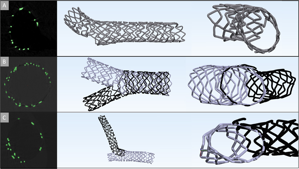
The provisional bifurcation technique, is the only procedure that consists of deploying a single stent. According to the European Bifurcation Club (EBC) this technique is recommended to be the first option when performing PCI in bifurcations; as it minimizes the amounts of foreign materials placed, it is not as technically demanding as other bifurcation techniques (A). Yet, doing this first, still allows for the possibility of additional stents to be placed if needed. In (B), a culotte technique is shown, which is considered to be performed when more acute angles occurs and where the branching vessels have similar diameters. A potential drawback of this technique is the resultant double stent layer proximal to the bifurcation; i.e., where the two stents overlap (B). A crush technique, shown in (C), is considered as one of the more technically demanding procedures; where a stent is implanted in the side branch first, and crushed along the vessel wall to allow for a secondary stent to be implanted. This will result in multiple layers of metal along one vessel section proximal to the bifurcation.
The ability to 3D model various bifurcation techniques has been extremely useful for analyzing the device-device and device-tissue interfaces, and how such a procedure may ultimately affect the resultant coronary flows. Analyzing these final bifurcation geometries and the steps taken to achieve their final outcomes has and will provide interventional cardiologists novel insights as to how to potentially optimize treatments for such patients. Additionally, this should also aid medical device designers in devising the next generations of drug eluting stents (DES).
Below is a procedure being performed on the Visible Heart® by visiting interventional cardiologists. Here we can see them performing a single stent, provisional, technique and building upon it to achieve a culotte by means of endoscopes, overhead cameras, and fluoroscopy. This video, along with many others, is available on the stents page of the Atlas of Human Cardiac Anatomy under device tutorials.